[6.3.1A.2] 成果
(1) 成果を図1に示す。
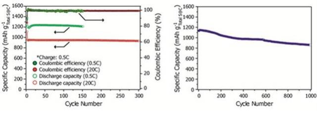
図1
(This figure is quoted from the document said above)
(2) 「電流レート」は「2C」である。
(3) ほぼ実用のレベルに達している。
(4) 「EV」の搭載して「試作車」を走らせてほしい。
[6.3.2A] 研究例(2A) New lithium/sulfur battery doubles energy density of lithium-ion
(Ⅵ) リチウム硫黄電池
[6.1] リチウム硫黄電池の概念
(1) 「リチウム硫黄二次電池」(以下「RLSB」という)は、空気電池以外では
最も「重量エネルギー密度」の高い二次電池である。
(2) 「硫黄」の「重量エネルギ密度」は「1675Wh/kg」と現行の「リチウム・イオン電池」の
「正極」のおよそ「200Wh/kg」と比較して非常に大きい。
(3) 「RLSB」は「負極」に「リチウム」、「正極」に単体の「硫黄」あるいは「硫黄化合物」を用いる二次電池である。
(4) 「正極」に用いる活物質の「硫黄」は安価であるから「RLSB」の低価格化を可能にする。
[6.2] 技術的な課題
[6.2.1] 正極の構造
(1) 放電の過程において「正極」では「硫黄」と「リチウム・イオン」が
反応して中間的な「放電生成物」である「硫黄化合物」の「L2S8」、「L2S6」、「L2S4」、「L2S3」、「L2S2」、
「L2S」まで生成される。
(2) 「L2S2」までの「放電生成物」は「電解液」に溶出する。
(3) そして「負極」の「リチウム」と反応して「自己放電」を生じる。
(4) 「L2S」は「電解液」に溶出しないで「正極」に析出する。
(5) そこで「多硫化リチウム」を「電解液」に溶出させないように種々の技術が提案されている。
[6.2.2] 電解質
[6.2.2.1] 液体電解質
(1) 「リチウム・イオン電池」で用いられているような「有機電解液」では「多硫化リチウム」の溶出が生じる。
(2) [6.3.6] で紹介されている「イオン液体」を用いる研究例がある。
この電解質では「多硫化リチウム」の溶出が生じない。
[6.2.2.2] 固体電解質
(1) [6.3.7]で示す「オークリッジ・ナショナル研究所」の研究例では
「lithium polysulfidophosphates」 (a new class of sulfur-rich materials
with good electrical conductivity)
という「固体電解質」を使って、「60℃」で「300回」の充放電のサイクルの後に
「1200mAh/g」の
「正極」の容量を維持する成果が得られている。
(2) しかしこの「固体電解質」の相対的に低い「イオン伝導率」のせいで
「出力密度」は「リチウム・イオン電池」に比べて小さい。
[6.3] 研究例
[6.3.1A]
研究例(A1) 「KAIST」の研究 (2013.12.4)
[6.3.1A.1] リチウム硫黄電池のシステム
(1) リチウムイオンよりも長持ちする「リチウム硫黄二次電池」を開発。
(2) 従来よりエネルギー密度5倍以上向上…1000回の充放電にも容量維持。
(3) 「KAIST」(韓国科学技術院、カン・ソンモ総長)は「新素材工学科」の「キム・ドギョン教授」と
「EEWS」の「チェ・ジャンウク教授」が共同で、現在商用化されている
「リチウム・イオン電池」より寿命と「エネルギ密度」が向上した「リチウム硫黄二次電池」を
開発したと「2013年12月3日」に発表した。
(4) 今回開発された「リチウム硫黄二次電池」は「単位重量」当りの「エネルギ密度」が
最大で「2100Wh/kg」と、商用化されている「リチウム・イオン電池」
(最大387Wh/kg)の「5.4倍」に達する。
またこれまでに開発された「リチウム硫黄二次電池」とはちがい、「数百回」の充放電が可能。
(5) 研究チームは「ナノ電極材料合成技術」を活用して「厚さ75nm(ナノメートル)」
「長さ15μm(マイクロメートル)」の「硫黄ナノワイヤ」を垂直に整列して
電極材料を製造した。
(6) この「硫黄ナノワイヤ整列構造」は「1次元構造体」であり、電子の速い移動が
可能なため電極の伝導度が向上した。
(7) また「硫黄ナノワイヤ」の表面に均一に炭素をコーティングし「硫黄」と「電解液」が
直接接触しないことから、充放電中に「硫黄」が溶けることを防止、
「RLSB」のもつ寿命の短さという問題を解決した。
(8) これまでに開発されている「RLSB」用の「電極」は
最初は高い容量を示すものの充放電を繰り返すと容量が持続的に減少した。
(9) しかし今回開発された「電極」は速い放電速度(3分ごとに1回の充放電条件)で
「300回」の充放電の後でも最初の容量の「99.2%」を維持、
「1000回」の充放電の後に「70%以上」の容量を示した。
(10) 研究チームは関連技術について「韓国国内特許」1件と「PCT国際特許」1件を出願した。
(11) 「キム・ドギョン教授」は
「このリチウム硫黄電池は無人飛行機、電気自動車および再生エネルギー貯蔵装置などに必要な
次世代高性能二次電池の実現を早めるのに役立つだろう。
リチウム硫黄電池の問題だった寿命低下の解決方案を提示できた」
と話している。
(12) 研究結果はナノ素材分野の国際学術誌「Advanced
Materials」に12月3日付で掲載された。
[6.3.1A.2] 成果
(1) 成果を図1に示す。
図1
(This figure is quoted from the
document said above)
(2) 「電流レート」は「2C」である。
(3) ほぼ実用のレベルに達している。
(4) 「EV」の搭載して「試作車」を走らせてほしい。
[6.3.2A] 研究例(2A) New
lithium/sulfur battery doubles energy density of lithium-ion
By Brian Dodson, Lawrence Berkeley Lab, December 1, 2013
[6.3.2A.1] 「RLSB」のシステム
(1) Batteries. We buy
them at the store, use them up, and throw them away without much thought.
(2) In reality, however, batteries are remarkably complex
electrochemical devices that are continually evolving.
(3) The latest
example of this comes from the Lawrence Berkeley National Laboratory,
where researchers have invented an advanced lithium/sulfur (Li/S) cell
that offers a unique combination
of energy storage, power, recharge
speed, and survivability.
(4) Lithium/sulfur
rechargeable batteries offer a remarkably large capacity for energy storage,
mainly because two electrons are produced each time a molecule is
processed through the battery's chemistry.
(5) The
voltage of a Li/S cell depends on the chemical entities in which electrical
energy is ...
(6) A basic Li/S cell consists of a lithium anode, a
carbon-sulfur cathode, and an electrolyte
that permits lithium ions to
pass.
(7) The overall cell reaction during discharge converts lithium
metal in the anode into Li2S
at the surface of the cathode.
(8) The flow of two lithium ions from the anode to the cathode is then
balanced
by the flow of two electrons between the battery contacts,
delivering double the current
of a Li-ion battery
at a voltage
between about 1.7 and 2.5 volts, depending on the state of charge of the cell.
(9) Lithium polysulfides are formed at intermediate charge levels,
which affect the cell voltage
as indicated above.
(10) That's
the good news. The bad news involves a host of materials problems associated
with the basic Li/S chemistry and some side reactions.
(11) When the sulfur in the cathode absorbs lithium ions from the
electrolyte, the Li2S has nearly
double the volume of the original
sulfur.
(12) This is a very large source of mechanical stress on the
cathode, which causes mechanical deterioration,
reduces the electrical
contact between the carbon and the sulfur
(the path whereby electrons
flow to allow the reaction to occur), and prevents the flow of lithium ions
to the sulfur surface.
(13) Another
problem is that lithium and sulfur generally don't react immediately to form
Li2S,
but rather get there through a series of intermediate species,
such as Li2S8, Li2S6, etc.
(14) Sulfur itself and Li2S are essentially
insoluble in the typical electrolyte used in Li/S cells,
but these
intermediate "polysulfides" often are soluble, which causes an ongoing
and severe loss of sulfur at the cathode.
(15) Other problems
appear, such as a roughening of the lithium anode surface with large charge
or discharge currents.
(16) All of these problems result in a
basic Li/S cell being a very bad battery.
(17) The
Li/S battery chemistry, however, offers the potential for such wonderful battery
performance that,
since its discovery in the 1960s, a lot of work has
been aimed at solving these problems.
(18) Engineers and scientists
have tried putting the sulfur inside nanochannels as well as
using
lithium-silicon-carbon alloy anodes, sulfur polymer cathodes, and a host of
other imaginative attempts at solving the interlocked Li/S battery
performance limitations.
(19) While a good deal of progress has been
made, development of a practical Li/S cell has eluded
researchers for
half a century.
(20) The
Lawrence Berkeley team addressed these problems by developing a nanocomposite
cathode
that addresses the three main problems presented by Li/S
cells.
(21) The new cathode material is a sulfur-graphene oxide
nanocomposite held together using an elastic polymer binder.
(22) Graphene
oxide is formed from graphite oxide by exfoliation, in which an ultrasonic field
is applied
to graphite oxide while suspended in water.
(23) The ultrasonic waves peel apart the layers of the graphite oxide,
producing very thin flakes of graphene oxide.
(24) These
flakes are then given a coating of sulfur a few nanometers in thickness.
(25) The thinness of the sulfur coating allows the sulfur atoms to make
good electrical contact
with the graphene oxide flakes.
(26) While not an excellent conductor of electricity, graphene oxide
has sufficient conductivity to
anchor the sulfur to the cathode,
thereby permitting a large flow of current to pass through the sulfur
layers.
(27) There
are intermediate products (lithium polysulfides) resulting from the operation of
a Li/S cell
that can dissolve into the ionic electrolyte of the cell,
thereby causing sulfur loss
and degrading the cell's storage capacity.
(28) One effect of putting the sulfur on the graphene oxide nanoflakes
is to protect one side
of the sulfur layer against this
degradation.
(29) In
the new Li/S cell, a protective surfactant is placed atop the sulfur layer to
also
protect its surface against dissolving in the electrolyte.
(30) Because the surfactant is cationic (attracted to the sulfur), it
will let the lithium anions through
to react with the sulfur of the
cathode while protecting the sulfur layer.
(31) As any lithium
polysulfides formed under the surfactant are trapped there, this addition nearly
eliminates the problem of sulfur loss.
(32) To
form a useful cathode for an Li/S cell, this loose collection of coated graphene
oxide nanoflakes
must be bound together to form a nanocomposite with a
very large surface area
that is accessible to the ionic electrolyte.
(33) Similar cells in the past have used 「polyvinylidene fluoride」, a
conducting polymer, as a binder material.
(34) However, such cells were
not able to long survive the enormous change in the volume of the sulfur layers
during charge and discharge of the cell.
(35) To ameliorate
this problem, the Berkeley team substituted an elastomeric co-polymer of
styrene butadiene rubber and carboxy methyl cellulose for the
binder.
(36) The electrolyte was also
changed in several ways from the traditional setup
(and this being
chemistry, you might need to brace yourself for some
challenging terminology here).
(37) While the same electrolyte salt
「(lithium bis(trifluoromethanesulfonyl)imide)」 was used,
the solvent was a
mixture of 「n-methyl-(n-butyl) pyrrolidinium bis(trifluoromethanesulfonyl)-imide
(PYR14TFSI)」,
「1,3-dioxolane (DOL), dimethoxyethane (DME)」
with 1 M
「lithium bis-(trifluoromethylsulfonyl)imide (LiTFSI)」, and 「lithium nitrate
(LiNO3)」.
(38) This
translates to combination which nicely balances the range of operating
temperature,
viscosity, and ionic conductivity required for efficient
Li/S cell operation.
(39) The tendency of the cell to form lithium
polysulfides was also reduced by the introduction
of the DOL and DME
fractions.
(40) The
lithium nitrate was added to reduce damage to the surface of the lithium metal
anode,
which had been observed to result from multiple charge/discharge
cycling.
(41) A traditional coated plastic separator (high porosity
polypropylene) was used to prevent
the flow of electrons through the
electrolyte while permitting free flow of the lithium ions.
(42) The result of these changes is greatly increased Li/S cell
performance.
(43) When the Li/S cell was charged and discharged at a
20-hour rate (C=0.05),
an initial specific energy of 500 Wh/kg (more
than twice that of Li-ion batteries) was still providing
as much energy
capacity as a fresh Li-ion battery after 1500 charge/discharge cycles.
(44) When the charge/discharge rate is increased to a one-hour rate
(C=1.0), the energy capacity
decreases by a factor of about 40-50
percent, but the cell continues to function well past 1,500 cycles.
(45) When
the Li/S cells were operated at very large power output
(C=6.0, meaning
that a cell would charge or discharge in 10 minutes) even after 150 cycles
the specific energy of the cell was larger than that of a fresh and
pampered Li-ion cell.
(46) This capability for very large power charge
and discharge was quite sensitive
to the amount of lithium nitrate
added to the electrolyte.
(47) The
potential price point for Li/S cells following the new design is potentially
as low as US$100/kWh of storage capacity.
(48) Beyond making
possible lithium/sulfur batteries with unprecedented specific energy, rate
capacity,
and long cycle life, many of the innovations made by the
Berkeley team may also be useful
in designing better and less expensive
Li-ion cells.
(49) The Li/S cell for the first time has demonstrated its
potential to challenge the dominant Li-ion battery
chemistry in the big
leagues of electric cars.
[6.3.2A.2] 成果
(1) 成果を図1、図2、図3に示す。
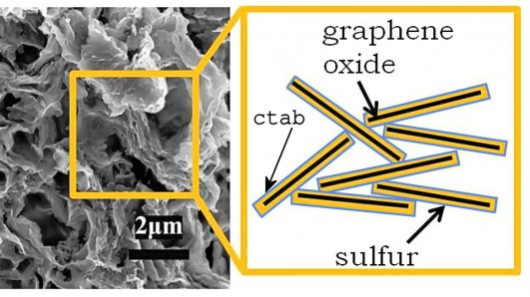
図1 A scanning electron micrograph of the nanostructure of the
cathode of a Berkeley Li/S cell
and a schematic of the layers in the structure ( Lawrence Berkeley Lab)
(This figure is quoted from the
document said above)
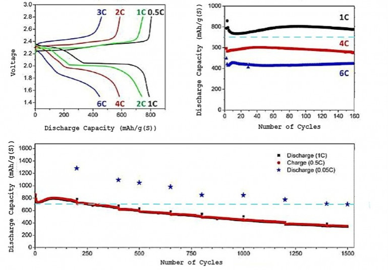
図2 Performance curves of a Berkeley Li/S cell. Charge/discharge voltage history
at extreme po...
(This figure is quoted from the
document said above)
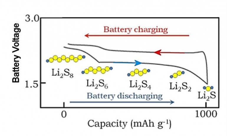
図3
(This figure is quoted from the
document said above)
(2) 電流レート「2C」では「700mAh/g」の「容量」である。
(3) この「RLSB」を搭載した「EV」の試作車を走らせてほしい。
[6.3.3A] 研究例(3A)
Graphene Oxide as a Sulfur
Immobilizer in High Performance Lithium/Sulfur Cells
Liwen Ji(1), Mumin Rao(2), Haimei Zheng(3), Liang
Zhang(4), Yuanchang Li(5), Wenhui Duan(5),
Jinghua Guo(4), Elton J. Cairns(2), and Yuegang
Zhang(1)
(1)
The
Molecular Foundry, Lawrence Berkeley National Laboratory, Berkeley, California
94720, United States
(2) Environmental Energy Technologies Division,
Lawrence Berkeley National Laboratory, Berkeley, California 94720, United
States
and Department of Chemical and Biomolecular Engineering,
University of California, Berkeley, California 94720, United States
(3)
Materials Sciences Division, Lawrence Berkeley National Laboratory, Berkeley,
California 94720, United States
(4) The Advanced Light Source, Lawrence
Berkeley National Laboratory, Berkeley, California 94720, United
States
(5) Department of Physics,
Tsinghua University, Beijing 100084, China
M.R. is a visiting researcher
from South China University of Technology.
L.Z. is a visiting researcher
from University of Science and Technology of China.
Received: July 25, 2011
18523
dx.doi.org/10.1021/ja206955k |J. Am. Chem. Soc. 2011, 133,
18522–18525
Journal of the
American Chemical Society COMMUNICATION
[6.3.3A.1] 「RLSB」のシステム
[Ⅰ] ABSTRACT
(1) The loss of sulfur cathode material as a result of polysulfide
dissolution causes significant capacity fading
in rechargeable
lithium/sulfur cells.
(2) Here, we use a chemical approach to immobilize
sulfur and lithium polysulfides via
the reactive functional groups on
graphene oxide.
(3) This approach enabled us to obtain a uniform and
thin (around tens of nanometers) sulfur coating
on graphene oxide sheets
by a simple chemical reactiondeposition strategy and a
subsequent
low-temperature thermal treatment process.
(4) Strong interaction between
graphene oxide and sulfur or polysulfides enabled us
to demonstrate
lithium/sulfur cells with a high reversible capacity of 「950-1400 mA h/ g」,
and stable
cycling for more than 50 deep cycles at 「0.1C」 (1C = 1675 mA/ g).
[Ⅱ] DESCRIPTION
(1) Elemental
sulfur (S) is very attractive as a cathode material for high-specific-energy
rechargeable
lithium batteries, because a battery based on the
lithium/sulfur (Li/S) couple would yield a
theoretical specific capacity
of about 「1675 mA h/ g」 with a
theoretical specific energy of 「2600 W h/
kg」 on the assumption
of the complete reaction of Li with S to form Li2S.
(2) In addition, S is also inexpensive, abundant, and nontoxic.
(3) Therefore, S is a promising cathode material for high specific
energy Li/S batteries.(1-15 )
(4) Despite
these considerable advantages, there are still a number of challenges in Li/S
batteries.
(5) The first one is the high electrical resistivity of
elemental S.
(6) The second one is the high solubility (in organic
solvent electrolytes) of the polysulfide
ions that are formed during the
discharge/charge processes.
(7) The soluble intermediate Li polysulfides
can diffuse through the electrolytetothe
Li anode wherethey are reducedto
form solid precipitates (such as Li2S or Li2S2).
(8) These reduced
products can also diffuse back to the cathode during recharging.
(9) These issues can lead to low active materials utilization, low
coulombic efficiency, and short cycle
life of the S electrode.(1-15)
(10) In
order to address these challenges, various carbon and conductive polymer
materials have been used to
accommodate S, to overcome its insulating
property and reduce the
dissolution of Li polysulfides, as reported by
「Nazar」, et al.(1,13,15 )and others.(4,6,7,10,12,16-22)
(11) The most
recent work by 「Archer」 et al. demonstrated that the mesoporous carbon/S
nanocomposites can
be cycled for 100 cycles at 「974 mA h/ g 」at a rate
of 「0.5C (1C =1675 mA /g)」
with the corresponding coulombic efficiency
of ∼96% and 94%, respectively,
at the first and 100th cycles.(23)
(12) Despite this progress, there are still few reports on fabricating
novel CS
cathodes via the chemical reaction
approach.(14)
(13) In this work, we used a low-cost and environmentally
benign
chemical reaction deposition strategy to immobilize S on
quasi two-dimensional
graphene oxides (GO) to prepare graphene oxide sulfur
(GO-S) nanocomposite cathodes
for
Li/S cells
in 「ionic liquid-based electrolytes」.
(14) We first deposited
nano-S onto graphene oxide (GO) sheets by chemical reaction in a
microemulsion
system (see experimental section in the Supporting
Information [SI] for details).
(Supporting Information is not
quoted here.)
(15) Then,
we heat treated the assynthesized samples in an argon (Ar) environment at
low
temperature (155 C) for 「12 h」 in order to remove some of the
bulk S
which is not directly attached to the 「GO」 layers.
(16) When the
as-synthesized 「GO-S」 nanocomposites were heat-treated in Ar,
the bulk S on
the external surface of the 「GO」 melted and diffused
into the pores of the
「GO」 due to the strong adsorption effects
derived from both the high
surface area and the functional groups
on the surface of the 「GO」.
(17) At the same time, this low-temperature heat treatment process can
partially remove and/or chemically
modify some of the functional groups on the 「GO」 surface
and improve the electronic conductivity
of the as-prepared
「GO-S」 nanocomposites
(see Table 1 in the SI).
(18) 「Figure 1a」 shows the scanning electron
microscope (SEM)
image of the as-prepared 「GO-S」 nanocomposite after heat
treatment.
(19) The layer-like extremely conjugated nanostructures
with
highly developed porous structures are clearly illustrated.
(20) The energy-dispersive X-ray (EDX) microanalysis in (Figure 1b)
con-firms the existence of S in the composite.
(21) As indicated in the
thermogravimetric analysis (TGA), about 66 wt % S is incorporated
into the
GO
after heat treatment (Figure S1, SI: not quoted).
(22) The transmission
electron microscope (TEM) image in (Figure 2a) and
the electron
energy-loss spectrum (EELS) in (Figure 2d) indicate that
a thin layer of S
with a thickness of tens of nanometers is
homogenously dispersed on the
flake-like 「GO」 surface with no
significant fraction of bulk S exposed on
the external surface of the
sample after heat treatment
(For comparison,
see the SEM
images for pure 「GO」 and SEM/TEM images for 「GO-S」
nanocomposites in
Figures S2 and S3 (SI) before heat
treatment ; not quoted).
(23) The
corresponding elemental mapping of carbon (Figure 2b), and S (Figure 2c)
display
a very similar intensity distribution, revealing a homogeneous
S
coating on the 「GO 」flakes in the as-formed 「GO-S」 nanocomposites.
(24) The
unique structure of the 「GO-S」 nanocomposite can improve
the overall
electrochemical performance when it is used as a cathode material for Li/S
batteries.
(25) First, it can accommodate the significant volume changes of S as
it is converted to Li2S on
discharge, and back to elemental S on
recharge.(110,17,24 )
(26) In
addition, the partially reduced 「GO」 with its large surface area
along with
ubiquitous cavities can establish more intimate
electronic contact with S and
avoid aggregation and loss of
electrical contact with the
current collector.
(27) Second, the lowtemperature heat-treated 「GO」 still contains various kinds of
functional groups (Figure S5, SI).
(28) These functional groups can have strong
adsorbing ability to anchor S atoms and to effectively
prevent the
subsequently formed Li polysulfides from dissolving
in the electrolyte during
cycling.
(29) We performed ab initio calculations to clarify the role
of
functional groups on 「GO」 in immobilizing S (see the calculation
methods
and detailed results in the SI).
(30) The results indicated that
both epoxy
and hydroxyl groups can enhance the binding of S to
the CC bonds due to the
induced ripples by the functional
groups (Figure 3a).
(31) We also performed soft
X-ray absorption
spectroscopy (XAS) measurement which probes unoccupied
electronic
structure and thus is a powerful tool for probing chemical bonding
in surface chemistry.
(32) (Figure 3b) shows the carbon K-edge
absorption
spectra for both 「GO」 and 「GO-S」
nanocomposites
(see S K-edge spectrum in Figure
S7, SI ; not quoted).
(33) The absorption features “A”,
“D”, and
“E”, which can be attributed to the π* state, excitonic state, and
σ*
state,25 are observed for
both samples.
Of note in the spectra
is the
increase in the sharpness of the π* and excitonic state for
GOS
nanocomposites as compared with GO, suggesting that the ordering of the
sp2
-hybridized carbon
structure is better formatted after S is
incorporated.
(34) In addition, feature “C” originating from a different
functional group (possibly the CO bond)
on the GO are weakened
significantly when incorporated with S,
which means strong chemical
interaction between S and the
functional group of 「GO」 happens
and S can partially reduce the
「GO」.(26)
(35) Besides,
a new feature “B”, originating from the CS σ*
excitations,27 is observed
for the 「GO-S」 nanocomposites.
(36) We
evaluated the electrochemical Li storage capability of these heat-treated 「GO-S」
nanocomposites
as potential cathode materials for Li/S cells in the
n-methyl-(n-butyl) pyrrolidinium bis-
(trifluoromethanesulfonyl)imide
(PYR14TFSI), Li-bis(trifluoromethylsulfonyl)imide
(LiTFSI), and
poly(ethylene glycol)
dimethyl ether (PEGDME, Mw =
250) mixture-based
electrolyte.
(37) (Figure 4a) shows the cyclic voltammetry (CV) profile of
one electrode.
(38) The measurement was conducted at a scan rate of 0.05
mV s1 in the voltage range of 1.0 to 3.6 V vs Li/Li+.
(39) During
the first cathodic scan, three main reduction peaks at around 2.4, 2.1, and 1.8
V were clearly shown.
(40) According to the reported mechanisms for oxidation and
reduction of S during discharge/
charge,(5,6,10,18,19,2831) the peak at
around 2.4 V can be assigned
to the reduction of elemental S to higher-order
Li polysulfides (Li2Sn, n ≧8).
(41) The
peak at about 2.1 V probably corresponds to
the reduction of higher-order Li
polysulfides to lower-order Li
polysulfides (such as Li2S6, Li2S4) from
Li2S8. (5,6,10,16-21,28-31)
(42) The
peak at 1.8 V is related to the reduction of polysulfide species to form Li2S.
(43) In the subsequent anodic scan, only one sharp oxidation peak is observed at
about 2.6 V that is attributed to the
complete conversion of Li2S and
polysulfides into elemental S.
(44) The main reduction peak is shifted to slightly
higher potential
and the oxidation peaks to lower potentials with increase in
cycle
number, indicating an improvement of reversibility of the cell with
cycling.
(45) In addition, as the cycle number increased, the oxidation peak at
2.6 V becomes less significant,
while another new one at 2.35 V grows higher
in intensity.
(46) The oxidation peak at 2.35 V is associated with the formation
of Li2Sn (n > 2).(23,29)
(47) After the second cycle, both the CV peak
positions and peak
currents undergo very small changes, indicating relatively
good capacity retention.
(48) The CV results show that 「GO」 can help to
prevent
S from dissolving into the electrolyte because of its large
surface along
with some functional groups on the surface.
(49) Figure 4b depicts the first and
second cycle discharge/charge
typical voltage profiles of the electrodes at
the 「0.02C rate (1C = 1675 mA/ g) 」between 1.0 and 3.0 V.
(The capacity values
in this article are calculated according to the mass of S.)
(50) All the
discharge curves show three plateaus in the voltage profile that
are
consistent with the peaks in the CV and are also well
documented in the
literature.(5,6,10,16,18-21,23,28)
(51) The GO-S nanocomposite delivers a high
initial discharge capacity of about
「1320 mA h/ g」 at「 0.02C」.
(52) The
corresponding coulombic effi-ciency in the first discharge/charge cycle is
96.4%.
(53) At the second cycle, a large reversible capacity of about 「1247 mA h/
g」 is
preserved (97.5% coulombic efficiency), corresponding to about 94.5%
capacity retention.
(54) This initial capacity loss is small compared
to the
formerly reported results of similar materials,(16,32) indicating
that the
strong 「GO-S」 interaction can reduce the dissolution of the
lithium
polysulfides into the electrolyte and thus minimize the shuttle phenomenon.
(55)
(Figure
4c) shows the cycling performance of the same cell cycled at a rate of 「0.1C」
after the initial two cycles at 「0.02C」.
(56) The discharge capacity of the
first cycle at 「0.1C」 remains at around 「1000 mA h/ g」.
(57) At the second cycle at
0.1C, this value decreases to about「 950 mA h/ g」.
(58) However, after more than 「50
cycles」 at the same rate, the reversible capacity remains at 「954mA h /g」
(with
a coulombic efficiency of about 96.7%), indicating
very stable reversibility
of the electrochemical reactions and excellent
capacity retention (also see
the cycle performance of another coin cell in Figure S10, SI).
(59) The
GO-S nanocomposites display improved coulombic efficiencies compared to the
former reports.23
(60) The discharge capacity of the GO-S was highly reproducible
over many coin cells.
(61) Another
example of the electrochemical
performance of the 「GO-S」 electrode is
demonstrated in (Figure 4d)
where a cell showed a reversible capacity of 「735 mA
h /g」 at「 0.5C」 after「 30 cycles 」at various rates.
(62) Further cycling at a low rate
of 「0.05 C」 brings it back to a reversible capacity of about「 1100 mA h/ g」
for
another 「20 cycles」.
(63) When this coin cell was discharged at a higher
rate of 「1C」, a reversible capacity of about 「550
mA/ g」 was obtained.
(64) The
last decrease of the rate to 「0.2C」, yielded a reversible capacity of about 「890 mA
h/ g」.
(65) When this coin cell was further discharged at 「2C」, an acceptable
reversible capacity of
about 「370 mA h/ g」 was obtained, indicating excellent
capacity reversibility and high rate performance
(see
the
corresponding discharge/charge profiles
in Figure S11, SI.; not quoted)
(66) The 「GO」 clearly performs very
well as a means to stabilize the S electrode.
(67) The 「GO」 provides highly
reactive functional groups on
its surface that can serve as immobilizers to
hold the S.(1,5,8)
(68) Also, by limiting the concentration of the polysulfide
anions in the
electrolyte, the redox shuttle phenomenon is largely
avoided.(1,8,9)
(69) The intimate contact of the S provided by the large surface
area
and the functional groups on 「GO」 is favorable to good electron/
ion
accessibility, leading to enhanced cycle performance and rate
capability.(19,17,20)
(70) In addition, the optimized
「ionic liquid-based electrolytes」 which have suitable viscosities and wetting
properties
influence the penetration of electrolyte into the S electrode
structure,
while increasing the ionic conductivity within the
electrodes at the
same time
(see control experiment in LiTFSIPEGDME-based electrolyte in
Figure S12,
SI ; not quoted).(5,33,34)
(71) In summary, a novel chemical approach is employed
to synthesize a 「GO-S」 nanocomposite
to immobilize S in
the cathode material of Li/S cells.
(72) The 「GO-S」 nanocomposite cathodes display good reversibility,
excellent capacity stability
of about 「1000 mA h/ g」, and rate capability
of up to 「2C」 in ionic liquid-based electrolyte.
(73) The 「GO」 in the
heat-treated composites has good conductivity and an extremely high surface
area, and
provides a robust electron transport network.
(74) The
functional groups on the 「GO」 surface play the role of immobilizers that
keep
intimate contact of the conducting matrix with S species,
and
effectively confine any polysulfides from dissolving.
(75) The 「GO」 network
also accommodates the volume change of the electrode
during the LiS
electrochemical reaction.
(76) As
a result, reversibility and high rate discharge capability were obtained.
(77) The same strategy could be helpful to explore and develop new
porous
carbon(35,36) or conductive polymer-based S nanocomposite cathodes
for advanced Li/S cells.
[Ⅳ] REFERENCES
(1)
Ji, X.; Lee, K. T.; Nazar, L. F. Nat. Mater. 2009, 8, 500–506.
(2) Hassoun,
J.; Scrosati, B. Angew. Chem., Int. Ed. 2010, 122, 2421–2424.
(3)
Kolosnitsyn, V.; Karaseva, E. Russ. J. Electrochem. 2008, 44, 506–509.
(4)
Yang, Y.; McDowell, M. T.; Jackson, A.; Cha, J. J.; Hong, S.
S.;
Cui, Y. Nano Lett. 2010, 10, 1486–1491.
(5)
Shim, J.; Striebel, K. A.; Cairns, E. J. J. Electrochem. Soc. 2002, 149,
A1321–A1325.
(6) Choi, Y.-J.; Chung, Y.-D.; Baek, C.-Y.; Kim, K.-W.; Ahn,
H.-J.;
Ahn, J.-H. J. Power Sources 2008, 184,
548–552.
(7) Liang, C.; Dudney, N. J.; Howe, J. Y. Chem. Mater. 2009,
21, 4724–4730.
(8) Ji, X.; Nazar, L. F. J. Mater. Chem. 2010, 20,
9821–9826.
(9) Gao, X.-P.; Yang, H.-X. Energy Environ. Sci. 2010, 3,
174–189.
(10) Lai, C.; Gao, X. P.; Zhang, B.; Yan, T. Y.; Zhou, Z. J. Phys.
Chem. C 2009, 113, 4712–4716.
(11) Ryu, H.-S.; Ahn, H.-J.; Kim, K.-W.; Ahn,
J.-H.; Lee, J.-Y. J. Power Sources 2006, 153, 360–364.
(12) Wang, J.; Yang,
J.; Xie, J.; Xu, N. Adv. Mater. 2002, 14, 963–965.
(13) Ji, X.; Evers, S.;
Black, R.; Nazar, L. F. Nat. Commun. 2011, 2, 325.
(14) Wang, H.; Yang, Y.;
Liang, Y.; Robinson, J. T.; Li, Y.; Jackson,
A.;
Cui, Y.; Dai, H. Nano Lett. 2011, 11, 2644–2647.
(15) He, G.; Ji, X.; Nazar,
L. Energy Environ. Sci. 2011, 4, 2878–2883.
(16) Cao, Y.; Li, X.; Aksay, I.
A.; Lemmon, J.; Nie, Z.; Yang, Z.; Liu, J.
Phys. Chem. Chem. Phys. 2011, 13,
7660–7665.
(17) Chen, S.-R.; Zhai, Y.-P.; Xu, G.-L.; Jiang, Y.-X.; Zhao,
D.-Y.; Li,
J.-T.; Huang, L.; Sun, S.-G. Electrochim. Acta 2011, 56,
9549–9555.
(18)
Jeon, B. H.; Yeon, J. H.; Kim, K. M.; Chung, I. J. J. Power Sources 2002, 109, 89–97.
(19) Liang, X.; Wen, Z.; Liu, Y.; Zhang, H.;
Huang, L.; Jin, J. J. Power Sources 2011, 196, 3655–3658.
(20) Wang, J.;
Chew, S. Y.; Zhao, Z. W.; Ashraf, S.; Wexler, D.; Chen,
J.; Ng, S. H.; Chou,
S. L.; Liu, H. K. Carbon 2008, 46, 229–235.
(21) Yuan, L. X.; Feng, J. K.;
Ai, X. P.; Cao, Y. L.; Chen, S. L.; Yang,
H. X. Electrochem. Commun. 2006, 8,
610–614.
(22) Wang, J.; Chen, J.; Konstantinov, K.; Zhao, L.; Ng, S. H.;
Wang,
G. X.; Guo, Z. P.; Liu, H. K.
Electrochim. Acta 2006, 51, 4634–4638.
(23) Jayaprakash, N.; Shen, J.;
Moganty, S. S.; Corona, A.; Archer,
L. A. Angew.
Chem., Int. Ed. 2011, 50, 5904–5908.
(24) Ji, L.; Tan, Z.; Kuykendall, T. R.;
Aloni, S.; Xun, S.; Lin, E.;
Battaglia, V.; Zhang,
Y. Phys. Chem. Chem. Phys. 2011, 13, 7170–7177.
(25) Skytt, P.; Glans, P.;
Mancini, D. C.; Guo, J. H.; Wassdahl, N.;
Nordgren,
J.; Ma, Y. Phys. Rev. B 1994, 50, 10457.
(26) Chen, W.; Yan, L.; Bangal, P.
R. J. Phys. Chem. C 2010, 114, 19885–19890.
(27) Pasquali, L.; Terzi, F.;
Montecchi, M.; Doyle, B. P.; Lukkari, J.;
Zanfrognini, B.; Seeber, R.; Nannarone, S. J. Electron Spectrosc.
Relat.
Phenom. 2009, 172, 114–119.
(28)
Yamin, H.; Peled, E. J. Power Sources 1983, 9, 281–287.
(29) Aurbach, D.;
Pollak, E.; Elazari, R.; Salitra, G.; Kelley, C. S.;
Affinito, J. J. Electrochem. Soc. 2009, 156, A694–A702.
(30) Jung, Y.; Kim,
S. Electrochem. Commun. 2007, 9, 249–254.
(31) He, X.; Pu, W.; Ren, J.; Wang,
L.; Wang, J.; Jiang, C.; Wan, C.
Electrochim. Acta 2007, 52,
7372–7376.
(32) Wang, J.-Z.; Lu, L.; Choucair, M.; Stride, J. A.; Xu, X.;
Liu, H.-K.
J. Power Sources 2011, 196, 7030–7034.
(33) Shin, J. H.;
Cairns, E. J. J. Power Sources 2008, 177, 537–545.
(34) Shin, J. H.; Cairns,
E. J. J. Electrochem. Soc. 2008, 155, A368–A373.
(35) Long, J. W.; Dunn, B.;
Rolison, D. R.; White, H. S. Chem. Rev. 2004, 104, 4463–4492.
(36) Ji, L.; Lin, Z.; Alcoutlabi, M.;
Zhang,
X. Energy Environ. Sci. 2011, 4, 268
[6.3.3A.2] 結果
(1) 結果を図1、図2、図3、図4に示す。
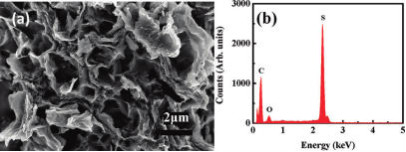
図1 SEM image (a) and EDX spectrum (b) of the GO-S
nanocomposite
after heat treatment in Ar at
155
(This figure is quoted from the
document said above)
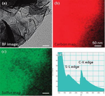
図2 TEM bright field (BF)
image (a) and the corresponding
elemental mapping for carbon
(b) and S (c) reveal a homogeneous S
coating on the GO flakes.
EELS spectrum is shown in (d).
The scale bars are 50
nm.
(This figure is quoted from the document said
above)
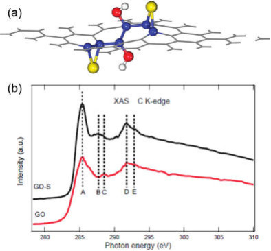
図3 (a) Representative
pattern of GO immobilizing S.
The hydroxyl enhances the
binding of S to the CC bond due to the
induced ripples by
epoxy or hydroxyl group.
Yellow, red, and white
balls denote S, O, and H atoms, respectively,
while the
others are C atoms.
Note that the C atoms bonding to S or O
are highlighted as blue balls.
(b) C K-edge XAS spectra of GO
and GO-S nanocomposites after heat
treatment in Ar at 155 C
for 12 h.
(This figure is quoted from the document said
above)
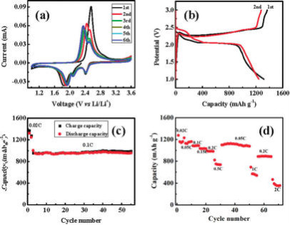
図4 (a) CV curve at
0.05 mV s1 scanning rate;
(b) galvanostatic discharge/charge
profiles at 0.02C rate;
(c) cycling performance at a constant
current rate of 0.1C after initial activation processes at
0.02C
for two cycles;
(d) reversible capacity
vs current density (rate capability).
The GO-S nanocomposites
were heat treated in Ar environment at 155 C for 12 h.
(This figure is quoted from the document said
above)
[6.3.3A.3] 評価
(1) 「グラフェン・オキサイド」の効果が主張されている。
(2) 「電流レート」が「2C」だと「400mAh/g」まで容量が落ちるからまだ実用的ではない。
[6.3.4A] 研究例(4A)
Energy & Environmental Science Issue 10,
2014
Improved lithium–sulfur batteries with a conductive coating on the separator to
prevent
the accumulation of inactive S-related species at the cathode–separator
interface
Hongbin Yao,(a) , Kai Yan,(a), Weiyang Li,(a),
Guangyuan Zheng,(b), Desheng Kong,(a),
Zhi Wei Seh,(a), Vijay Kris Narasimhan,(a), Zheng
Lianga and Yi
Cui,(a,c)
Energy & Environmental Science, 2014,7,
3381-3390
DOI:
10.1039/C4EE01377H
Received 03 May 2014, Accepted 14 Jul
2014
First published online 07 Aug
2014
[6.3.4A.1] 「RLSB」のシステム
(1) Improved
lithium–sulfur batteries with a conductive coating
on the separator to
prevent the accumulation of inactive S-related species
at the
cathode–separator interface bottom
(2) Lithium–sulfur (Li–S) batteries
are highly attractive for future generations of portable electronics
and electric vehicles due to their high energy density
and potentially low cost.
(3) In the past decades, various novel
electrodes and electrolytes have been tested
to improve
Li–S battery performance.
(4) However, these designs on electrodes
and electrolytes have not fully addressed the problem
of
low cycling stability of Li–S batteries.
(5) Here, we show the role
of the separator in the capacity decay of the Li–S battery,
namely that it can accommodate a large amount of
polysulfides inside which then precipitates
as a thick
layer of inactive S-related species.
(6) Using a thin conductive
coating on the separator to prevent the formation of the inactive
S-related species layer, we show that the specific
capacity and cycling stability
of
the Li–S battery are both improved significantly compared to the
battery with a pristine separator.
(7) Combining this separator design with a monodisperse sulfur
nanoparticle cathode,
we show Li–S batteries with
a life of over 「500 cycles」 with an initial specific capacity
of 「1350 mA h/ g」 at「 C/2」 and a cycle decay as
low as 「0.09% 」per cycle.
[6.3.4A.2] 結果
(1) 結果を図1に示す。
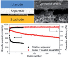
図1
(This figure is quoted from the document said
above)
(2) 「電流レート」は「0.5C」である。
(3) 「500サイクル」の後でも「1350mAh/g」の容量を維持しており、 「0.09%」しか劣化していない。
(4) かなり実用的レベルに達しているのではないか?
*******
A PART END ********
[6.3.1] 研究成果(1)
Improving lithium-sulfur batteries for
greater energy density
(September
26, 2014) Paul
Dvorak
[6.3.1.1] 「RLSB」のシステム
(1) This article comes from
Nano Letters and will be of interest to who wish to stabilize their grids.
A search for the next great
high-energy, rechargeable battery technology has been on for a while.
(2) Recently, scientists report they have overcome key obstacles toward
making lithium-sulfur (Li-S) batteries,
which have potential to
outperform today’s lithium-ion technology.
(3) This study appears in the
ACS journal Nano Letters.
(4) To better confine the sulfur/polysulfides
in the electrode of lithium–sulfur (Li/S) batteries
and improve the
cycling stability, we developed a double-layered core–shell structure
of
polymer-coated carbon–sulfur.
(5) Carbon–sulfur was first prepared
through the impregnation of sulfur into hollow carbon spheres
under
heat treatment, followed by a coating polymerization
to give a
double-layered core–shell structure.
(6) From the study of scanning
transmission electron microscopy images,
we demonstrated that the sulfur
successfully penetrated through the porous carbon shell
and aggregated
along the inner wall of the carbon shell, which, for the first time,
provided visible and convincing evidence that sulfur preferred diffusing
into the hollow carbon rather
than aggregating in/on the porous wall of
the carbon.
(7) Xingcheng Xiao, Weidong Zhou, Mei Cai
and colleagues point out that the capabilities of lithium-ion batteries,
which power many of our consumer electronics, as well as electric
vehicles, have largely plateaued.
(8) Scientists have been pursuing a
number of new battery technologies to topple today’s standard.
(9) One
heavy focus has been on a key battery component that is currently made out of a
metal oxide.
(10) Some researchers have been trying to replace the metal
oxide with cheaper and lighter sulfur,
to make Li-S batteries.
(11) In theory, this could allow batteries to pack five to eight times
the energy of existing technology.
(12) One of the main problems with
this approach, however, is that Li-S compounds escape from where
they’re supposed to be, which causes the battery to lose charge
quickly.
(13) The team set out to find a way to contain the errant
compounds.
(14) To solve the problem, the researchers made tiny, hollow
shells out of carbon, which is conductive.
(15) They then coated them
with a polymer to help confine the Li-S compounds inside.
(16) When
tested, the structures kept up a high-energy storage capacity
(630
mAh/g versus less than 200 mAh/g of lithium-ion batteries) over 600 cycles
of fast charging and discharging.
(17) “These results provide
promising insights and novel concepts for future sulfur-based batteries,”
the researchers conclude.
[6.3.1.2] システムの特徴
(1) 「正極」の「硫黄」を被覆している。
[6.3.1.3] 結果
(1) 結果を図1に示す。
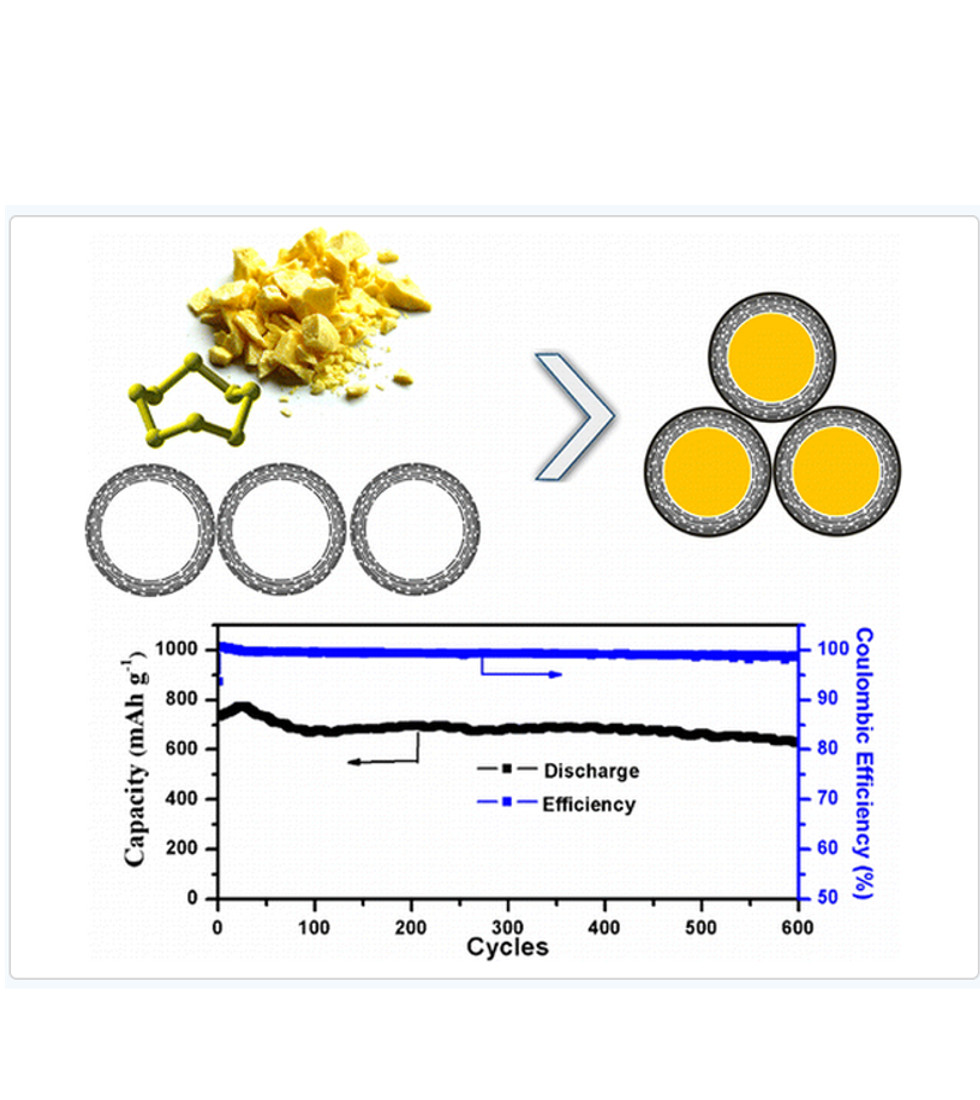
図1
(THIS FIGURE IS QUOTED FROM THE DOCUMENT SAID ABOVE)
(2) 「600サイクル」で「600mAh/g」の容量を維持している。
(3) 電流レートは「0.6C」と思われる。
[6.3.2] 研究成果(2)
Dr. Vasant Kumar at the University of Cambridge and
Professor Renjie
Chen at the
Beijing Institute of
Technology
Graphene sheet-sulfur/carbon composite cathode
for higher performance Li-sulfur batteries
(16 December 2014)
[6.3.2.1] リチウム硫黄電池のシステム
(1) A team of researchers led by
Dr. Vasant Kumar at the University of Cambridge and Professor Renjie Chen
at the Beijing Institute of Technology has devised a three-dimensional
hierarchical sandwich-type
graphene sheet-sulfur/carbon (GS-S/CZIF8-D)
composite to address performance-related issues
in
Lithium-sulfur batteries such as low efficiency and capacity
degradation.
(2) The thin graphene sheet, wrapped around the sulfur/zeolitic
imidazolate framework-8
derived carbon (S/CZIF8-D) composite, has
excellent electrical conductivity and mechanical flexibility.
(3) This
facilitates rapid electron transport and accommodates the changes
in volume of the sulfur
electrode.
(4) Compared with an unwrapped S/CZIF8-D sample, Li-S
batteries with the GS-S/CZIF8-D
composite cathode showed enhanced
capacity, improved electrochemical stability up to 120 cycles,
and
relatively high Coulombic efficiency.
[6.3.2.2] 条件
(1) 「硫黄」を閉じ込めている。
[6.3.2.3] 結果
(1) 結果を図1に示す。
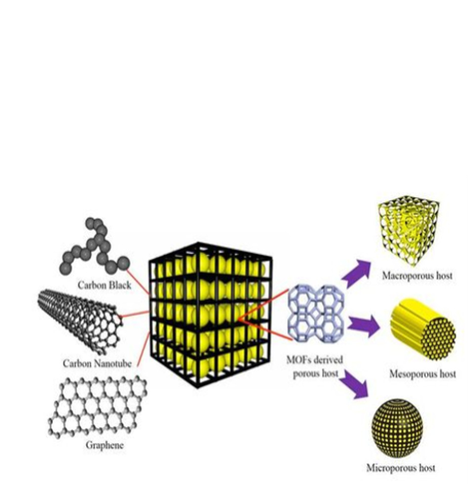
図2-F
(THIS FIGURE IS QUOTED FROM THE DOCUMENT SAID ABOVE)
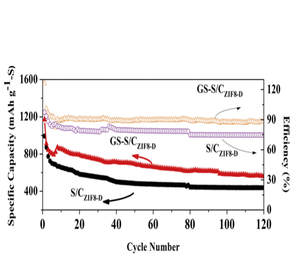
図1
(THIS FIGURE IS QUOTED FROM THE DOCUMENNT SAID ABOVE)
(2) 「120サイクル」で「700mAH/g」の容量を維持している。
(3) 電流レートは不明。
[6.3.3]
研究成果(3)
A
highly efficent polysulfide mediator for lithium-sulfur
batteries
Nature Communications Vol.6, Article;
5682
DOI: 10.1038/ncomms6682 REceived 23 Sep ,2014,
Acc 27 Oct. 2014, Pub 06 Jan
2015
(Department of Chemistry, University of Waterloo,
200 University Avenue West, Waterloo,
Ontario, Canda, N2L 3G1)
Xiao Liang, Connor Hart, Quan Pang & Linda F.
Nazar
(BASF SE, 67056
Ludwigshafen,Germany)
Arnd Garsuch, Thomas
Weiss
[6.3.3.1] リチウム硫黄電池のシステム
(1) The lithium–sulfur battery is
receiving intense interest because its theoretical energy density
exceeds that of lithium-ion batteries at much lower cost, but practical
applications are still hindered
by capacity decay caused by the
polysulfide shuttle.
(2) Here we report a strategy to
entrap polysulfides in the cathode that relies on a chemical process,
whereby a host—manganese dioxide nanosheets
serve as the prototype—reacts
with initially formed lithium
polysulfides to form surface-bound intermediates.
(3) These function as
a redox shuttle to catenate and bind ‘higher’ polysulfides, and convert them
on reduction to insoluble lithium sulfide via disproportionation.
(4) The sulfur/manganese dioxide nanosheet
composite with 75 wt% sulfur exhibits a reversible
capacity
of 1,300 mA h g−1 at moderate rates and a fade
rate over 2,000 cycles of 0.036%/cycle,
among the best reported to
date.
(5) We furthermore show that this mechanism extends to graphene
oxide and suggest it can be
employed more widely
[6.3.3.2]
結果
(1) 結果を図1に示す。
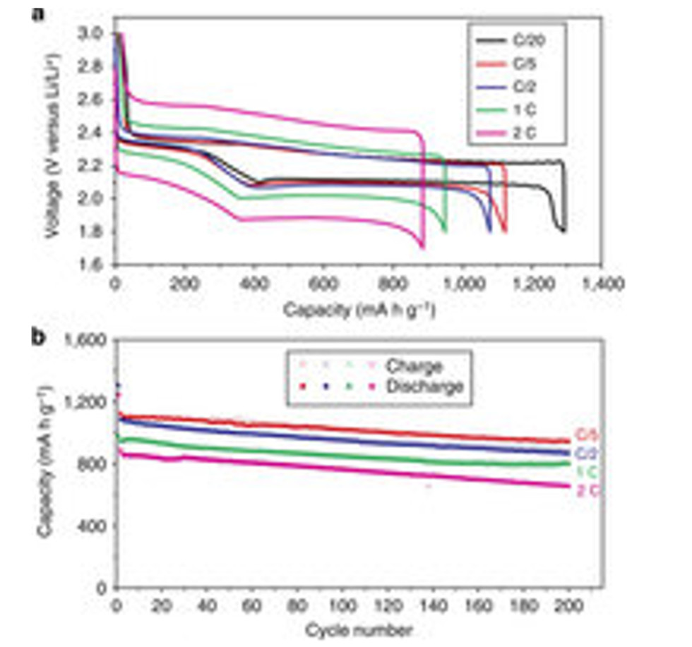
図1
(THIS FIGURE IS QUOTED FROM THE
DOCUMENT SAID
ABOVE)
(2) 「2C」で「200サイクル」で「600mAh/g」の容量を維持している。
(3)
「600mAh/g」の容量は現行の「リチウムイオン電池」の「4倍」もある。
(4) 「リチウム硫黄電池」では「電圧」が「半分」であるから「重量エネルギ密度」は「2倍」である。
[6.3.4] 研究成果(4)
A group of researchers led
by Professor Lee Jae-young
at the Gwangju Institute of Science and
Technology
The results of the development were published in the
online version of ChemSusChem on April 29
with the title of
“Improvement of energy capacity via Vitamin C-treated dual-layered
graphene-sulfur cathodes
in lithium sulfur battery”.
[6.3.4.1] システム
(1) 「正極」の構造を工夫している。
(2) Researchers develop 20% improved lithium-sulfur
battery for electric cars using vitamin C
may 15, 2015 by admin leave a
comment
(3) Korean researchers have developed a new type of lithium–sulfur battery
using 「vitamin C」 with a 20% improvement in performance over current ones.
(4) A group of researchers led by Professor Lee Jae-young at the Gwangju
Institute of Science and Technology
said on Thursday that they succeeded in
improving the energy capacity of lithium–sulfur batteries
with vitamin C
treated dual-layered graphene–sulfur.
(5) 「Lithium-sulfur batteries」 are widely considered as a viable replacement for
current 「lithium-ion batteries」
for electric cars because of its superior
energy density.
(6) Yet, 「lithium-sulfur batteries」 have not been actively used in
the field yet since there are
a few problems to be resolved such as poor
cycle performance and low charge/discharge rates.
(7) However, the researchers showed that their 「vitamin C treated dual-layered
cathode」,
which is composed of a 「sulfur active layer」 and a 「polysulfide
absorption layer」,
can increase sulfur utilization dramatically resulting in
a lithium-sulfur battery with a high specific capacity
of over
「600 mAh/g(sulfur)」 after 「100 cycles」 even under a high current rate of 「1C」.
(8) Professor Lee said,
“This development is meaningful in a sense that it
can greatly improve low cycle performance
of lithium-sulfur batteries, which
is a big obstacle to commercialization of them,”
“we expect the
new development will practically increase the adaptation of lithium-sulfur
batteries to next-generation electric car batteries.”
[6.3.4.1] 研究結果
(1) 図1に研究結果が示されている。
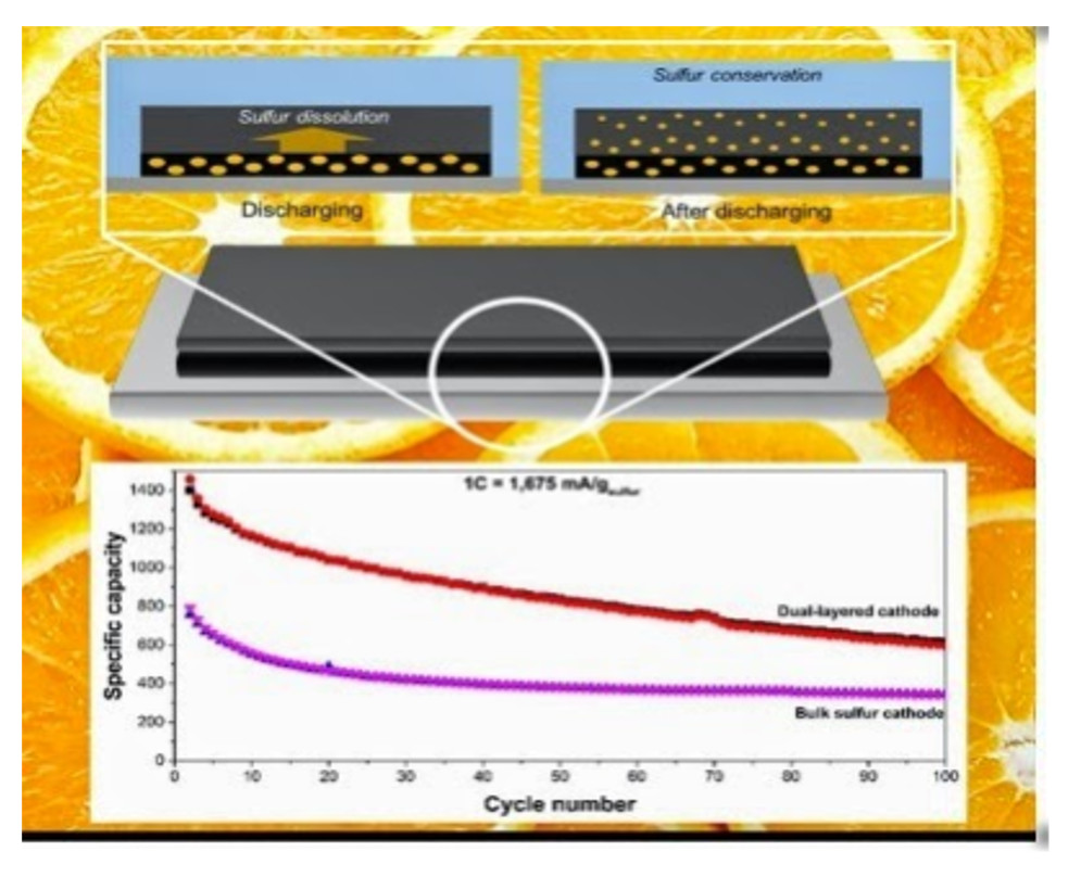
図1
(THIS FIGURE IS QUOTED FROM THE DOCUMENT SAID ABOVE)
(2) 電流レートは「1C」でのデータである。
(3) 「100サイクル」で「600mA/g(sulfur)」の容量であるが、サイクルとともに
劣化傾向を示している。
[6.3.5] 研究成果(5)
New
Lithium-Sulfur Battery With Cycle Performance Comparable To That Of
Lithium-Ion Batteries & Double The Energy
Density
Clean Technology Wednesday, April 15, 2015
[6.3.5.1] システム
(1) A new lithium-sulfur battery that demonstrates cycle
performance that's comparable to that
offered by currently available
commercial lithium-ion batteries and possesses roughly twice
the energy
density has been developed by an international team of researchers
from
South Korea and Italy.
(2) This research team — which was led by
researchers from 「Hanyang University」 —
utilized a highly reversible
「dual-type sulfur cathode 」(solid sulfur electrode and polysulfide catholyte)
and a 「lithiated Si/SiOx nanosphere anode」, in order to achieve its new
results.
(3) A new research paper from the group explained that the new
lithium-sulfur battery
delivered a specific capacity of ∼「750 mAh /g」
over 「500 cycles 」(85% of the initial capacity).
(4) The reason for the
impressive new results (possibly), according to those involved,
is as a
result of a synergistic effect between the enhanced electrochemical performance
of the new anode and the optimized layout of the cathode.
(5) While the new work won’t result in lithium-sulfur batteries replacing
lithium-ion ones tomorrow,
it does bring the commercial viability of
the technology one step closer —
as the new work has addressed some of
the primary issues with the technology.
(6) The researchers designed a LiS cell using a dual-type hybrid sulfur
cathode
and a lithiated Si/SiOx nanosphere anode with an optimized
liquid electrolyte.
(7) The cathode consists of an activated
carbon−sulfur composite
on a gas diffusion layer (GDL) electrode in
contact with a catholyte solution
to which 「Li2S8」 has been added.
(8) This cathode system delivers a maximum capacity of ∼「1300 mAh /g」
with respect
to the overall mass of sulfur (about 1.2 mg) from both the
solid sulfur
(about 0.2 mg on the electrode) and the dissolved lithium
polysulfide
(1.024 mg in 80 μL of the polysulfide-containing
electrolyte).
(9) At a rate of 「C/3」, the cathode shows a capacity of ∼「1000 mAh/ g」;
Coulombic efficiencies of more than 99.3% except for the first cycle;
and a maintenance of the capacity above 99% of the initial capacity
even after 100 cycles.
(10) The 「lithiated Si/SiOx nanosphere anode」
used shows highly stable cycling behavior
over 「100 cycles」 with a
capacity of as high as 「800 mAh/ g」
and cycling efficiency approaching
100%.
(11) The full lithium-ion sulfur cell presented in the study
delivers a capacity
of ∼「750 mAh/ g」 with an average working voltage
of about 「1.8 V」,
corresponding to the energy density of 「497 Wh /kg」
based on the weight of active materials
on the cathode and anode.
(12) Very interesting.
While I personally don’t expect
lithium-sulfur batteries to replace lithium-ion batteries
anytime in
the near future for most applications (and never at all for some applications),
the technology does seem to be improving fairly rapidly.
It’ll be interesting to see how it ends up being utilized.
(13) The new findings were detailed in a paper published in the journal Nano Letters.
[6.3.5.2] 研究結果
(1) 図1に研究結果を示す。
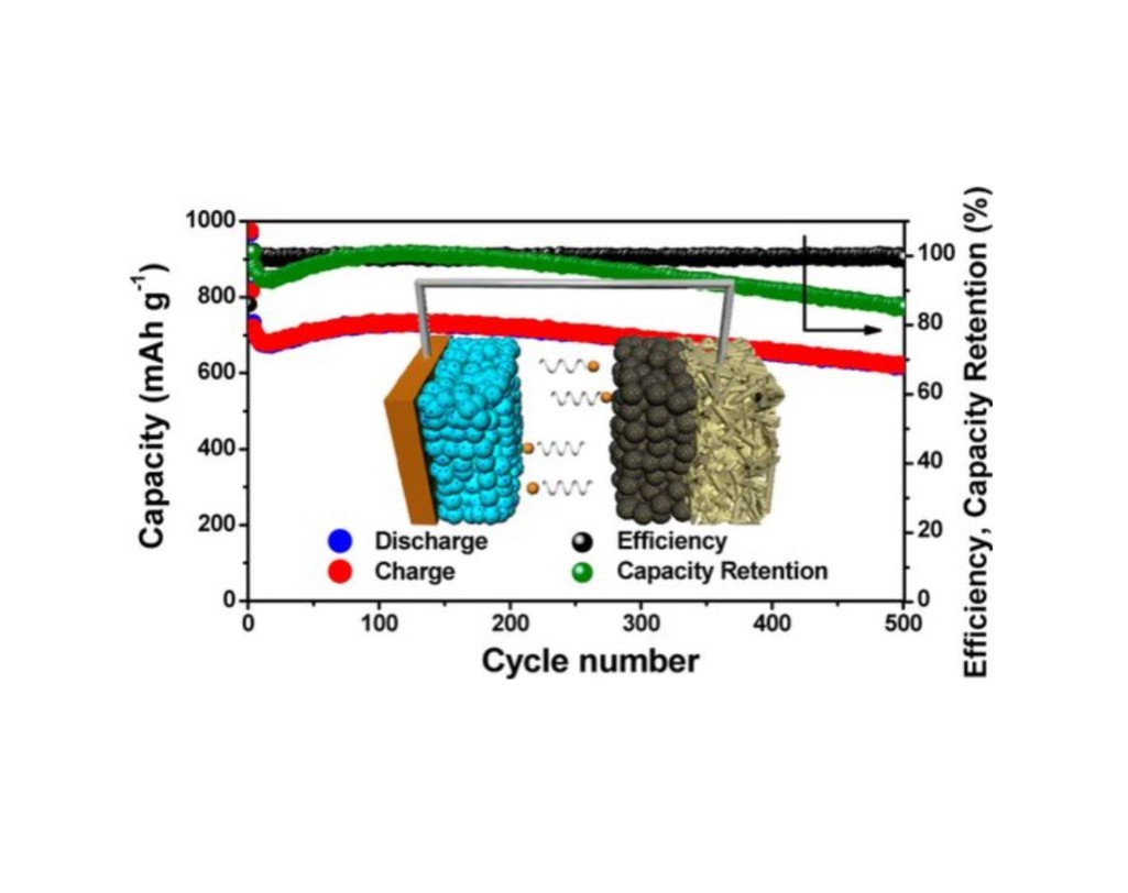
図1
(THIS FIGURE IS KUOTED FROM THE DOCUMENT SAID ABOVE)
(2) 電流レートは 「C/3」のデータである。
(3) 「500サイクル」では「700mAh/g」の容量が得られている。
[6.3.6]
研究成果(6)
「イオン液体」を用いた次世代リチウム二次電池の構築
渡邉正義 横浜国立大学大学院工学研究院
[6.3.6.1] リチウム硫黄電池のシステム
(7) In previous Li-S battery designs, the
electrolyte used was liquid in nature.
(8) This proved a double-edged
sword:
the liquid electrolyte is an excellent conductor because of how
it dissolves the lithium compounds,
but this dissolution also causes
the battery to break down
prematurely.break down prematurely.
(9) The liquid electrolyte is
also flammable, posing serious safety concerns.
(10) But
now, researchers may have found a way around these problems.
(11) "Our
technology overcomes the capacity fade and safety issues of Li-S technology,"
Dr. Chengdu Liang, lead author of a paper on the research, told
Gizmag.
(12) "The battery still performs well after a few hundred
cycles, and the volumetric density could be
slightly better than
Li-ion batteries."
(14) Even
after 「 300 charge-discharge cycles」 at 「60°C (140ºF)」, the battery retained
a capacity of 「1200 mAh/g」, compared to the 「140-170 mAh/g」 of a
traditional 「lithium-ion battery」
(lithium-sulfur batteries, however,
only deliver about half the voltage of lithium-ions, so this 8-fold increase
actually translates into a 4-fold increase in energy density).
(15) The
battery uses elemental sulfur, which is a byproduct of industrial petroleum
processing.
(16) In other words, the battery could also provide a way
to recycle industrial waste into a useful – perhaps
even superior –
technology.
(17) "The
main limitation is the relatively low ionic conductivity of the solid
electrolyte,"
said Liang.
(18) "So the power density is lower
than Li-ion batteries, but it can be improved with a better solid electrolyte.
Moreover, the ceramic structure is brittle, and much optimization is
needed."
(19) The
technology is still in the early stages of development, but Liang and colleagues
are working on ironing out
these issue and have filed a patent
application for their battery design.
(20) The
paper detailing the study was recently published in the journal 「Angewandte Chemie」.
(21) Gizmag wrote back to Dr. Chengdu Liang
for more details of the battery's charging and discharging behavior.
(22) Here is his response:
(23) "We
did not observe self-discharge.
A charged cell was put on shelf for
over a week, and it still delivered the same capacity.
(24) The essence
of our all-solid battery design is to eliminate the self-discharge
through the all-solid configuration.
(25) "This
battery charges slower than Li-ion battery at the current status for a simple
reason;
the ionic conductivity of both the solid electrolyte and
cathode are not high energy
to have high current density.
Much better performance at elevated temperatures such as 60 degrees C
or higher."
[6.3.7.2] 成果
(1) 「300回」の充放電サイクルの後でも「60℃」において
「1200mAh/g」の容量を維持している。
(2) 現行の「リチウム・イオン電池」の「140-170mAh/g」の「電流容量」に比較して
「電流容量」では「8倍」であるが、「電圧」が「半分」であることを考慮すると、
「重量エネルギ密度」としては「4倍」になる。
(3) しかし「固体電解質」では「出力密度」は「リチウム・イオン電池」に比べて小さいのが課題である。
[6.3.8] 研究成果(8) Impressive
graphene-based cathode for lithium-sulfur
batteries
Graphene applications Batteries Technical / Research
Source: cleantechnica Apr 20, 2015
[6.3.8.1] リチウム硫黄電池のシステム
(1) Researchers at Beihang University in China developed
new cathode materials
for lithium-sulfur batteries, made from vertically
aligned sulfur–graphene (S-G) nanowalls
on electrically conductive
substrates.
Impressive cathode for lithium-sulfur batteries image
(2) These
new cathodes are reported to allow fast diffusion of lithium ions and electrons
and achieve an excellent capacity
(of 1261 mAh g–1 in the first
cycle, and over 1210 mAh g–1 after 120 cycles)
and high-rate performance
(more than 400 mAh g–1 at 8C, 13.36 A g–1).
(3) The scientists claim
that these impressive figures position it as the best demonstrated rate
performance
for sulfur-graphene cathodes.
(4) The researchers
believe that this new work may open the door to new approaches
to the
manufacture of graphene-containing composites with unique structures
“for catalysis, sensors, and energy storage and conversions.”
[6.3.8.2]
研究結果
(1) 図1に結果を示す。
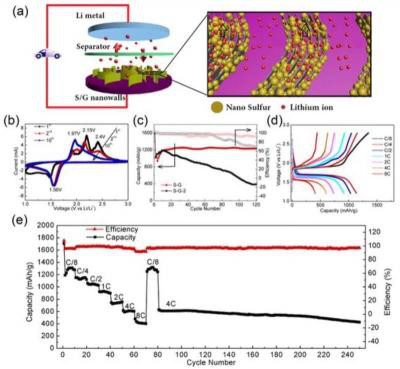
図1
(THIS FIGURE IS QUOTED FROM THE DOCUMENT SAID
ABOVE)
(2) 電流レートは「2C」で容量は「700mAh/g」もある。
(3) 充分に実用的レベルに達している。
(4) この「RLSB」を搭載した「EV」の「試作車」を走らせてほしい。
Célèbre beaux arts du
monde